This looks like a recipe for cold solder joints and solder bridges and doesn't seem like it saves time.
What you really want to do when you have dozens of jumper wires is to do an array-of-struct to struct-of-array transform on the steps. Instead of cutting, stripping, tinning, and soldering one wire at a time, cut all your wires, then strip them all, then tin them all, then solder them one by one.
Here's a pro tip: when you tin the wires, lay the iron flat on your workbench with tip out into air and tin by laying the end of the wire on top and then adding the solder.
Another pro tip: use a pair of needle nose pliers to bend the tinned leads by a little over 90 degrees to make a little hook. When you solder to the board you can apply a little tension and let the solder flow into the hole. Makes very string solder joints.
If you have that many stripped wires to tin, you can use a tub of flux and a solder pot. Dip the wires into the flux, then quickly dip it into the solder pot. Perfectly tinned end with no plastic melting. Really hard to mess up vs a soldering iron, a wire, and solder wire.
You can even dip multiple wires into the flux and solder bath at the same time, as well as use the flux tub again before you solder the tinned wire to the contact.
> Because the metallic conductor is essentially a mirror at the wavelength of the laser, the process is effectively “self terminating”, that is the laser vaporises all of the insulating material down to the conductor and then stops, so no process control is required to prevent damage to the conductor.
> The Mercury-4 is the culmination of years of research
I'm imagining some researcher after years of investment and experimentation eventually accidentally discovering the solution: "you mean it just shuts _itself_ off?!?!".
It doesn't shut itself off. It just stops cutting. It's like using concrete as a kitchen cutting board: that knife isn't going to do any damage, regardless of whether or not you stop pushing.
If you want to laser through metals, you need a different type of laser. Just as getting through concrete needs a different tool (say, a hammer chisel).
Totally true, but you don't always have a solder tub or tub of flux laying around. The other advantage of this approach is it's easier to avoid tinning under the insulation
I did several years in production engineering. We never used flux. Not once. It’s a crutch for people who don’t know how to solder.
What we did was use solder that wasn’t shitty. Big fan of felder 62/36/2 but it ain’t cheap.
We also cleaned stuff properly before soldering it. The reason people tend to flux things to death is that they didn’t clean the oxide layer off before soldering. Or used shitty solder.
felder 62/36/2 [0] is a flux-cored solder. So you were using flux every time.
It's also a leaded solder, which is much easier to get nice joints from than lead-free.
Flux is great, adding some before you solder is a good tip, and will likely help you make better joints if as you said, you haven't perfectly cleaned everything. The only downside is perhaps some more cleanup afterwards. There's no reason to disparage it's use.
So flux is 'a crutch for people who don't know how to solder', because that knowledge would lead you to use 'expensive' flux-cored solder instead of 'shitty solder' plus flux?
I really don't think either's wrong, and anyway I assume 'production engineering' is not using how-to-solder tutorials.
Ding ding ding. Production soldering isn't easy, but it's much easier to dial in than rework jobs. It's definitely a desirable goal to not need flux for production work.
I most certainly do not use flux in my rework. I am in a zero-clean facility, the only flux allowed is that which comes with the solder paste for stencil and SMT placement - on initial production work.
Fluxless rework isn't difficult at all. I do it dozens of times a day.
I'm having a little trouble believing you unless by "rework" you meant "reflow".
Production reflow without extra added flux is normal. It's the goal for every assembly line anywhere and is almost always achieved.
Rework of existing joints after assembly without flux is just about impossible. The oxidation of the joints guarantees it. Many times the flux in the paste or wire is sufficient, but this is more true for through-hole than for surface-mount, mainly due to joint geometry and available volumes. If you are regularly reworking old fine-pitch surface mount joints previously assembled with no-clean flux, without flux of your own... then I'd like to know what materials you're using, because that is not possible in general. The "no-clean" fluxes are notorious for causing rework trouble, and they are difficult to clean off once reflow temperatures have been achieved (that's why we call them "can't-clean"). They are never active twice, so they must be removed and replaced once heated the first time. We have to use special solvent flux removers around here (based on DuPont's hellish Vertrel XF) to get the crap off just to be able to access joints again. (This is on assembly work done out-of-house or on COTS devices, made with who-knows-what.)
"I'm having a little trouble believing you unless by "rework" you meant "reflow"."
Nope, we don't use flux at all for rework. As the majority of our boards are solid metal, we just slap them on a heater and poke the components down or slide them into place. Flux isn't needed. Even with crappy RoHS tin solder. If you're getting significant-enough oxidation that interferes with rework with the product fresh out of the oven, or even a day or two later, you're doing something extremely wrong. Check and make sure your production paste isn't contaminated.
"It’s a crutch for people who don’t know how to solder."
This needs shouting from the rooftops.
So many people get sucked into the groupthink on this; yes it helps with less-than-perfect beginner's soldering skills, but it should not be normalized.
Flooding every joint with extra flux is unnecessary and a waste of money.
We all don’t get to work on nice, new, shiny PCBs. Sometimes other things get in the way. I have three different kinds of flux, two types of solder, copper wick, three solder suckers, two guns, and a scratch pen. I’m not out to practice the art, I just want to be effective.
Most soldering that relies on effects from solder surface tension simply will not work without quite a bit more flux than you can get from the core of a solder wire. Drag soldering, for example, won't work on quad flat pack chips without quite a bit of flux.
And while my techs will absolutely back you up that my soldering skill sucks, to a person they ALL use solder flux for their soldering. Not even a single exception. And they're all trained to NASA aerospace standards.
Now, maybe you can be more skilled than they are and get away without using solder; however, back down here in reality, the rest of us punters will just add flux when soldering stuff, thanks.
I agree up to... new parts shouldn't need cleaning. And cheapo hobbyist-grade RF and audio connectors often have a weird chrome + some kind of oil or varnish surface finish that just won't clean off or solder and flux is a godsend for those.
That said, I let someone borrow my bottle of liquid flux about a decade ago and have never bothered to replace it.
> do an array-of-struct to struct-of-array transform on the steps
I call this "pin-making" after Adam Smith's famous/apocryphal account of the division of labour in a pin factory [0] and do it in pretty much every area of my life :)
Another pro tip, get a better soldering iron than the one in the video.
Soldering stations aren't cheap (Hakko is my somewhat-budget-friendly favorite) but that (plus good solder) will make you realize you've been able to solder all along: it's just that you were using crappy tools.
A few years back I bought a Chinese hot air rework station for <$200. Maybe like “Ayoye” or something with a lot of vowels. It has a soldering iron with a vacuum pump as well.
I never really use the hot air part but am in love with the iron. I can dial in the temp and avoid breathing fumes directly. It is so much nicer to use than my old Weller with a temp dial.
The Aoyue hotair station I have has a soldering iron which is a clone of a hakko 936. Uses the same tips even.
I almost exclusively use my Metcals now...the Aoyue has a tip for inserting heat set brass inserts to 3d prints nowadays, I don't use it to solder much.
Sidenote: My hotair station is almost 8 years old...still works fine. So for the money it was worth it for sure.
Yeah, I have been disappointed with Weller. Still, anything's probably better than the Radio Shack pencil iron I started out with (and thought I was bad at soldering).
I dont do a ton but for me it always seemed like the weak point was the grip was 3+ inches from the tip. If I am soldering something that is just a couple mm from the hole next to it then this requires a decemt amount of dexterity - even if things are held nicely.
The base with temperature control and a fine-ish tip is what makes them good, I think. The older Radio Shack pencil soldering irons had a fat tip, one temperature.
The nicer stations like Hakko's have very nice metallurgy in their tips as well.
As soon as you get a station too there's a little sponge, maybe some metal wool — these things you can use to clean the tip of the soldering iron. That in itself encourages good soldering hygiene and makes for better soldering.
Yeah my kit came up a sponge and station too - but unmounted was so lightweight it was worthless. Perhaps a safety threat but I (with my amateur perspective) still think a shorter length would be very beneficial if possible.
Look for an iron with a ceramic heating element as well - they come up to temperature much more quickly and it makes a big difference. I also recommend Hakko.
Oh boy, nice idea, but this looks complicated and time consuming. I recommend to get some good equipment first:
  - solder fume extractor (see below)
  - extra thin high quality tin
  - a desoldering pump AND desoldering wire
  - high quality flux
  - a TS 100 soldering Iron with KU tip from ali express for 50 bucks
  - optional: USB-C Power Adapter for your existing power supply (so you don't have to buy one)
  - optional: a soldering mat (normaly blue colored)
and you have a near professional equipment for about $120. Now flash IronOS[1] on your soldering Iron, and it works even better.
Instructions:
  - turn on solder fume extractor
  - heat iron to 370° Celsius (but be careful depending on your workpiece)
  - Tin both ends beforhand
  - better slightly more flux to put on (but not for small works)
  - if flux has been applied, cleaning up with e.g. toothbrush & isopropyl alcohol after you're done maybe a good idea
However, the most important peace of hardware is a solder fume extractor... I'm surprised that so many youtube "professionals" don't put a hint on this - never play with your health. This can even be done DIY (see youtube tutorials).
High quality flux is also important because of your health. Chinese sellers often don't care about ingredients...
High quality tin is much easier to work with and costs 5 bucks more than low quality tin. It is worth.
Or get a $25 Pinecil that comes with IronOS pre-installed and is by all accounts almost as good as the TS-100 [1] (it's $40 on Amazon now :/). I got one, was so impressed that I got another. One big upside over the TS-100 for me is that it can be driven by both a beefier USB-C (which I always have around anyway) and DC-plug PSU.
Plus, it's running Risc-V, and they even sell an breakout to use the "logic board" as a RISC-V dev-board!
I got to here and thought this was some elaborate joke, and expected the github page to continue on with the joke. An operating system for a soldering iron?? But no, it seems 100% serious. Somehow soldering iron tech passed me by.
Anything more than your basic soldering iron is probably running a PID loop to control temperature. I don't know if my hakko is supported by IronOS but I could easily see it as a useful option.
It's the flashlight guys who have really run amok:
The Pinecil V2 has a new processor with Bluetooth. I'm a little fuzzy on whether it offers WiFi as well, but Pine64 suggested it could be used to automatically activate a fume extractor based on the tip temperature. Home Assistant integration wouldn't be hard.
I actually did set up a smart plug for my soldering iron in Home Assistant [1]. I set it up with a timer and presence detection (using my phone and watch) so that I don't leave it on by accident.
After reading this thread, it sounds like I need to get myself a better soldering iron and install IronOS
Agreed on the flux, agreed on the metcal. And oh yes, silver bearing solder is really nice. I only use it for repairs of solder joints that have failed mechanically. If you use it for everything, that solves that problem... but a little rich for my blood.
Hobbyists and technicians get obsessed with cleaning off flux. Hobbyists have no business cleaning flux off boards. It's very easy to wind up freeing corrosive salts from the rosin matrix. Then they smear all over the board to corrode and conduct. My rule of thumb is if you can't measure the cleanliness of your board, don't clean it.
Yep. To be honest a lot of stuff we didn't clean flux off professionally. Anything which was solvent safe would be soldered on, the board cleaned, then anything not solvent safe would be soldered on and it'd be left.
100% on the fume extractor. Avoid the cheap little "carbon filter" models though. You need particulate filtration and a bit of organic vapour extraction, so HEPA +/- carbon if you are going to recirculate it within your work environment.
Don't take my word for it, it's all explained in the NIOSH and OSHA handbooks.
You don't get the same exposure from working in a shop soldering all day than from the occasional hobby project. And if you have a simple fan, you are already doing more than most hobbyists.
Safety is not priceless. Regulators carefully calculate how much impact various safety equipment and practices have relative to their cost. And you too should consider how much you need it. Solder for hours a day, get the best fume extractor you can find, do a hobby project every other month, you can go cheap.
Anyways, I wonder if a simple small desk fan fitted with a surgical mask you probably have too much of would be a good compromise of simple, cheap, and better than nothing for hobbyists.
I have never bothered, personally, even when I built more of my own prototypes myself. Hobbyists should consider their personal risk and go in increments. If you are not in a situation where setting up monitoring for exposure to flux per the NIOSH handbook is appropriate, you probably don't need much mitigation either. Putting solder assemblies at a level where flux smoke won't go up into your face is a good idea and practically free. A fan is a good idea, especially if you have one already.
If you're fixated on getting yourself a fume extractor... well, to each their own.
As someone aspiring to solder more, thanks for this list! Do you have any thoughts on the TS 100 vs the Pinecil? I thought the Pinecil was a slightly newer and more refined iron but curious if you have an opinion.
I did have issues with 2 Pinecils breaking on me. The first one they replaced under warranty. I still use a 3rd I have, so I don't mind recommending it because I can get a Pinecil for cheaper than a TS100, and I doubt you'll get better support for a TS100 if something does come up within the warranty period.
Oh I should mention I have both the TS100 and Pinecil, and the Pinecil does everything the TS100 does.
Not the original commenter, but the pinecil has been serving extremely well for a while now. I ordered it when it launched and probably use it every two weeks.
Full disclaimer I know some people had trouble with the USB-C power input so YMMV, but considering the price it's probably the most cost-effective tool I ever bought.
No, I did never own a Pinecil, but the TS100 is just awesome, but the KU tip is even more important. It looks too big for fine work, but it isnt. I soldered a broken backlight fuse for my T480s with this (that's proably the tiniest thing ever soldered without a heat gun).
This sounds like way too much. Yes, with an iron you don't have the luxury of going just above melting point. It's a balance between heating up workpieces quickly (so that heat does not conduct too far) for what you need higher temperatures, not burning the flux and solder solidifying as quick as possible, because any movement in solidifying solder WILL reduce quality of the solder. Lower temperatures are almost always better than high temperatures.
You are better off getting powerful iron with good temperature control rather and keeping temperatures in working range rather than heating iron to very high temperatures and having it cool down during soldering if the iron cannot keep up with cooling. For soldering wires to a breadboard it may not be much of a problem (sans insulation burning off), but I would not risk damaging silicon with temperatures that high.
With 60/40 solder temperatures around 300 [290-310] are usually more than enough, depending on workpiece size.
The TS100 is apparently not recommended for IronOS according to their README. Curious why you chose that one over, for instance, a recommended TS80P or better a Pinecil V2? Full disclosure: I have a 15 year old Weller WD1 so I don't know much about this.
> How big of a deal is solder fumes of unleaded solder?
Worse than leaded solder, because the temperatures are higher.
The lead in leaded solder doesn't go up in fumes. Contamination is from touch. You should wash the board after you're done (with e.g. IPA) and your hands.
You also should try and not solder where you eat, and the other way around.
Not really, I bought a used one with a simple replaceable active carbon filter and place it near the open window. The most important thing is, that it is powerful enough to really EXTRACT and filter the fumes, not spread them in the room.
If you are in the basement without window, you probably need a better one with HEPA + active carbon.
I would say for hobbyists you should spend around 20 - 50 bucks for a used one.
Maybe also care about the loudness... these things are really bad ;)
Bad advice. Just use a good solder iron, thin solder (possibly leaded), and good no clean flux, then lots of practice. It's all about timing: too quick = cold solder joint; too slow = burned pad/track, or part. Learn also to understand about thermal mass and how to change the temperature and timings according to what you're soldering and its size.
Also, that iron looks like a Hakko "936" cheap clone: they are barely above the garbage level; get a better one. Used Wellers aren't that expensive, and no, you won't need a microcontroller for digital temperature control and all those gimmicks they put in modern solder irons. I also have a PineCil from the same folks that made the PinePhone and was amazed by its quality. Yes, it has a mcu for digital temperature control, but I'd lie if I wrote that I used any of its functions beyond setting the temperature.
The PineCil looks like a TS100 clone, though I'm not too sure which came first. The huge benefit of these microcontroller irons are their monolithic heating element that integrates the temperature sensor. This allows for much better temperature control compared to cheap Hakko-style irons where the tip is a metal piece that sleeves over the heating and sensing elements. It makes a very meaningful improvement in terms of the time it takes to heat up parts with high "thermal inertia"
TS100 was first. I believe the Pinecil also takes TS100 tips.
I've liked the Pinecil except sometimes mine crashes in the middle of me soldering. I need to update the OS but I'm lazy. It does fail cold (Says it's hot but it's not heating) which is probably the better of the two ways it could go.
There have been reports of defective Pinecil batches, this was after I bought mine and before the newer ones were introduced. There are also reports about fakes sold around, which is not a good thing in this case since the original is already very cheap and 100% Open Source, bot hardware and firmware, and fakes are of inferior quality.
The defective batches were among the originals though, but it seems they already solved all problems.
IMO, the killer feature of the Pinecil is that it takes both direct DC power input (like a TS100) and USB-C (like TS80). It's a great versatile little iron. While I have both a Hakko and Weller, I often reach for the Pinecil because it just feels fun to use.
I like my Metcal and wouldn't be without it. But by most accounts the '936 clones do fine with real Hakko tips.
A lot of technicians seem to like to have temperature knobs so they can dial the temperature around instead of swapping out for an appropriately sized tip: this works of course except when it doesn't.
The problem with Hakko clones aren't just the tips but the handpiece whose thermal contact between the heater and the tip is often unreliable, and the low thermal mass makes it hard to solder bigger tabs without raising the temperature to absurd levels. I swapped 3 hand pieces and two heaters on mine before giving up, reverting for a while to my two 40 years old gun shaped irons (25W and 100W) then getting used Wellers, then finally the Pinecil, which I mostly bought because I wanted to support the Pinephone project, and then revealed itself as a really nice and functional solder iron.
Best I saw during my apprenticeship days in the 1980s was when we had some EE degree students on work placement.
We worked in R&D and all (Multibus II) boards were hand-soldered and had to be visually inspected by a supervisor before testing.
One chap presented his board for checking and, after a visual and touch inspection, our supervisor said that some of the joints were a bit 'pointy' and would need fixing.
So off went the student to the fab area of the workshop, the board was put in a vice and I just stopped him as he approached the bench with a sandpaper-wrapped block of wood.
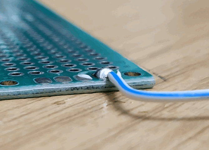
The OP uses single stranded wire but the solder blob on the PCB creates far more surface area contact for heat transfer from the iron which makes a large difference with stranded wire. When you're soldering hundreds of connections, the time savings from not having to pin the wire against a solid surface or clip it in place is substantial.
The bigger problem is that all the rosin flux in the solder will have evaporated, likely making the joint very weak. Most DIY projects lack any form of strain relief so it's a double whammy for any wire that will shift around.
>"The bigger problem is that all the rosin flux in the solder will have evaporated"
But the OP specifically adds short pieces of solder to the pads before soldering wires. When they finally lay the wire and start heating that solder piece might have just enough flux in it. Alternatively one could just smear some flux on the pad before laying wire.
Still I am not convinced this particular way is of any practical advantage.
Flux helps break the surface tension between solder blob and wire so I really doubt the flux in the unmelted solder would have a path to flow to the wire.
But yeah, my solution is to just dip the wire in a jar of flux as I’m stripping and twisting them
Not just the wire...the entire joint needs to be heated equally (ideally) and then the solder is touched to the heated joint. Any time you touch the solder to the iron it will burn off the flux and cause cold joints.
Never put solder on the iron tip...although...I do it sometimes to increase heat transfer to larger joints (emulates a larger tip) but you can expect that the flux has burned off and may require liquid flux and reflow.
Sidenote: if you coat your tips with solder before shutting off your iron it will prevent oxidation and increase tip life.
You should avoid soldering when possible because connectors are detachable for module maintenance and solder is prone to cracking in high vibration environments. Typically you will see a connector soldered and otherwise secured mechanically to a PCB where vibrations are unavoidable.
This is probably true for scaled production, BUT...
Most people following Instructables for tips on soldering wires to vector boards aren't likely to need to maintain their prototypes, and roughly 0% of those prototypes will be in a high-vibration environment.
Soldered connections can be surprisingly crap (intermittent electrical gremlins) especially if you're a noob. You can't easily spot a cold solder as a noob. Meanwhile even a noob can easily judge basic crimp quality. Better to get an all-in-one box assortment of cheap male and female connectors off eBay
I started out soldering but now it's mostly limited to installing connectors into PCBs followed by hot glue around the housing for mechanical rigidity
For wires like the ones in the video you can still use something like a small phoenix connector and just screw your wire connections in, just like you would wire up a choc box, no crimp tools required.
The advice in the post will likely create a cold joint and intermittent/noisy connections.
And intermittent problems make newbies lose motivation extra quickly and care even less until they eventually rage quit. It's better to just get connections done well right away
Crimping is better if you're an industrial facility and you can afford to scrap a few parts working out how to crimp them.
If you're an individual making runs of 1 and you have to crimp a different connector to a different wire every time, soldering is easier and more likely to result in a reliable connection.
Crimping is pretty easy if you have the right tool - not the "free" one made from stamped metal that comes with those cheap boxes of red/blue/yellow connectors, which crushes the connector flat rather than allowing it to retain the springiness on which a good crimp relies. I'd say that it's easier than soldering, but the tools are roughly comparable in price. However there is rarely a choice to be made: if you're attaching to a circuit board you're going to have to either solder wires on, or solder a connector (even if the wire or cable going to the connector is crimped). I just use crimping for motorcycle electrics, where vibration is an issue.
Crimping works really well when the parts are sized appropriately for each other (the correct size wire and matching-size terminal, for instance), AND when you have the exact correct crimp tool to do the crimping. Crimp tools can cost a small fortune, and are specific for the item they're crimping. You can't just use some generic crimp tool or pliers and get a good crimp connection. So in a factory setting with the correct parts and tools, crimps are actually superior.
For prototypes or one-offs, soldering as you say is more likely to be reliable.
It's not the thermostat but the power output that matters and a slightly more expensive soldering iron will generally have a slightly better power supply. For example, the best soldering iron I've ever used is the Metcal fixed temperature inductive soldering station which require changing out the tip alloy to change the temperature (and I've never had to change tips for temp, only shape).
The temperature you need is very dependent on the PCB. I have heard of macbook repair techs using 850-900C irons because of the amount of metal in that PCB and its heat dissipation capabilities. I usually end up around 700-750 for hobby projects with 2-4 layer PCBs because I like to do the joints fast.
Show me a professional soldering station that goes anywhere near 900C - I think most max out at 500. I doubt the tip alloys could withstand that heat very long. Sounds ridiculous. 700C is excessive for just about anything.
Metcal fixed temperature soldering irons use RF induction instead of resistive heating elements so they don't struggle with large copper pours like that. The soldering irons you're thinking of have very poor thermal recovery compared to a proper Metcal.
Electronics was my pandemic hobby. Even with a temperature controlled solder station, my technique was really hit or miss. Part of that is obviously experience, but the real lightbulb moment for me was good solder.
Once I switched to Kester solder, I had a much better more consistent experience. My hypothesis is that cheaper solder doesn't have the flux as evenly distributed, so you get spans of solder with too little flux and then everything gets worse, then you hit a good patch and it gets better.
Yes, flux is necessary. I use Kester solder, too :-)
P.S. I worked my way through college being an electronics assembly technician, so I spent a lot of time soldering. I enjoyed making the boards look perfect.
It turns out, this skill is transferable to soldering copper water pipes. Never had a leak! (Using a torch not an iron.)
The one I got is "Kester 24-6337-8800 50 Activated Rosin Cored Wire Solder Roll, 245 No-Clean, 63/37 Alloy, 0.031" Diameter". I have no idea which of those words and numbers are significant. :)
I didn't go lead-free because I've heard leaded solder is easier to use (lower melting point?) and since I'm just a part-time hobbyist, the health and environment considerations are minimal. It's not like I'm soldering eight hours a day every day.
Depends on the solder and the component, for wires there is no way to hurt it so you can crank up for efficiency, and for sensitive components you need to be more careful.
It’s actually much harder to make a good solder joint with lead free solder, so be kind to yourself about it. No harm in re-doing a joint.
You can get a cold joint that way. I went through the through-hole solder training for lead free solder, for manufacturing aerospace components back in the day. #1 thing they teach is not to do things like that, you need to heat the component and let the solder flow to the joint around the component, never heat the solder itself or pre-solder, etc.
You shouldn't really lap solder wires to boards. They tend to pull the pads off the boards or crack. Better to use wire to board connectors or solder terminals.
Those just starting out tend to think of solder as more direct than using a connector so therefore more secure.
But it’s surprising how poor the reliability can be. Aside from your points, solder can wick up a cable, and then the cable often breaks just at the point where the solder ends since it has no strain relief and may be right in the middle of a bend. This is especially true for adding solder to a crimped connector “for good measure”. It does more harm than good.
That being said it’s convenient many times especially if you don’t have connectors on hand or need to place wires in a specific orientation. Hot glue or better yet, RTV silicone can be used to make strain relief to increase the reliability. Or, when using perf board like in the post, a good technique is to drill a hole for a snug fit of the cable including insulation, then pass the cable through the hole before soldering to an adjacent hole.
It’s worth expanding on my comment now I have a few minutes. You can terminate solid core like this if it has some strain relief but not stranded!.
My favoured construction method is to take a Hammond box lid and screw a piece of blank FR4 single sided copper to the inside of it leaving enough space around the edges for any (proper) connectors you need. You can then drill out anything you need, usually BNC, SMA, DC jacks, FT capacitors and D connectors for me. You build the prototype on the FR4 board dead bug and use solid core or RG174 to wire up the connectors and lap solder them to the boards or components as required. This is done carefully with thought for weight distribution and to keep the total mass of the wires low. When it works the Hammond box is closed. If it needs to withstand vibration or moisture you build it into the bottom of the Hammond box and when done fill it with potting compound.
No, you shouldn't lap join wires to surface-mount pads. But sometimes you have to. Just don't deliberately design something this way and we'll call it good.
Yes, but if you do have to design a PCB for soldering wires to pads, you can increase the strength of the pad by making the pad much larger in the copper layer. You can still keep it the original smaller size in the solder resist layer; keeping the soldering area away from the pad edge and fragile traces there increases the strength further, and gives it a tidy look and a nice soldering experience.
For quick one offs, simply place a normal pad, place a copper fill polygon connected to the same net around the pad, and turn off thermal reliefs / set pad connection to solid for the polygon. Obviously if you need it a lot, draw a new footprint.
You need to nail the pad down with a few vias (under soldermask is fine) or use a through hole. Please just use a through hole if you can. They're a lot more reliable than just about anything else. Even SMT connectors rip off boards without much trouble. (This is my job. I have seen some things.)
There are some really cool surface mount IDC things too, and push-in terminators for solid wire.
Solid wire through holes is OK if the wire is never going to flex. Otherwise the stranded wire lapped to surface mount pads, or soldered into through holes, with a big blob of hot glue or epoxy for maybe-sorta "strain relief" is a great pet peeve of mine - it's ugly and it breaks.
It's the .154" Molex stuff that tends to melt after 20 years spontaneously. Not sure what plating they use bit it turns into a power dissipating resistor after a bit which is not good when you're shoving a few amps through it.
Molex is great if you get the reflow-compatible models. Their older lines with the non-updated parts do have some issues at high temperatures. If you really care, look for glow wire tested parts. Or just, y'know, keep your iron away from them and buy spares for when you don't....
I have done this stuff in production environments. Wires and connectors are like, 30% of the challenge on simple projects and can make or break the quality of a project.
You MAY have a chance if the wire is pretinned or you use flux. Do not do this with bare copper even if it looks like it works, you will probably get at least a few cold joints.
The better version is to coat the wire and pad with solder, put the wire on the pad, flux. then press it into the pad with the iron.
Better yet, never ever solder wire directly to a board in hobby or low volume work unless small size is totally critical. Especially stranded. It makes a metal fatigue point if things move at all, and requires hot glue to stand even a few bend cycles.
And even when you do have good connectors, it's probably still in your best interest to minimize the number of wires hanging around, learn about I2C as quick as you can.
It can't be quickly disconnected for repairs and replacement and troubleshooting.
It's a lot of work.
Even if done perfectly it's just not very nice.
Instead, solder connectors to the board directly. For short ranges use 2.54mm jumpers. Never use male jumpers if you can avoid it, they are delicate and annoying.
For longer distances, there are lots of things that don't suck, USB-C, 2.1mm barrel, Ethernet, 3 pin XLR, and whatever your country has for mains electricity.
Stay away from normal 4mn banana plugs unless you are in a field where they are already everywhere. The cheap ones shear off. and have bad connections and they are not particularly common. Even DMM test leads don't use them, they use the shielded versions.
Common off the shelf stuff that you can buy extensions for. Don't solder long wires to stuff, it will just make a tangled mess when you put it away and make it hard to troubleshoot.
When you do have a reason to do stuff like that, Wago connectors and pigtail adapters are your friend especially for tests and troubleshooting Because then when you realize you actually don't need 5 XT60 extensions, you can swap the ends for something else quickly.
And most importantly Do. Not. Invent. Some. Crazy scheme of powering all your projects from a central point over long 12v wires. Every new electronics DIYer seems to do it, and cables and wires are often the enemy. Yeah it looks cool and sci-fi and seems like a good idea to have wires everywhere, but single purpose and custom made cables are a nuisance to deal with, they're heavy and expensive and trip hazards.
That’s a neat looking trick, will have to see how well it works in practice. I can’t see it working too well if you need to feed the wire into a through hole.
My trick is to tin the joint and the wire, apply no-clean flux to either the joint or the wire (situation dependent), then bring the two together while reflowing the joint. Quite handy for soldering tight multi-pin connectors.
The real tip is buy flux, it’s just as important as solder.
Agreed on the through-holes, and doubly agreed on the flux. All magic in soldering ultimately comes from flux.
The other way you can easily solder to pads is to use solder paste. Many people don't seem to realize that paste is good for more than just reflow. It's not as useful for situations like this, where you need a relatively large solder volume (so I'd also use your method), but it works quite well for smaller scale work.
TAG-Connect makes a nice one of these. I use their target footprint on all my MCU projects now. The guide holes and pins make it easy to hold with one hand and know it will stay put as you initiate the programming with your other hand.
This is extremely useful to me as a _hobbyist_. Many of the critiques in this thread are valid, but probably not relevant to the hobbyist environment.
For me, I struggle to get solder even in the best of circumstances. It's just a skill that I cannot master. I really, really like this technique as it enables me to make passable hobby solders without risking messing up my project.
As a hobbyist, I've had my fair share of cold solder joints*, so I flinched when I saw what the linked article recommends. I once did something similar with cheap perf board, and ended up scrapping it because they can only take so much rework before the traces are destroyed.
The only "good" I see in this is that they author has left a rat-tail of unmelted solder so at least it will have some flux left to wet the wire.
* which show up as intermittent opens at DC with some fun dependence on position / temperature / humidity. At audio frequencies, they're disastrous -- I can only imagine what they'd do at HF.
Surely unrelated but I remember being 15 (30 years ago) and being an electric guitar player with modest or no economic resources.
I'm not saying that I celebrated the moment when one of my wires or jacks broke, but it felt great fixing it with a little patience and some soldering.
I am close now to many musicians that never fixed any of their wires/cables.
The last few years I’ve been getting out and playing guitar with more people. The thing I found most surprising was how most guitar players don’t know how to fix their guitars. I genuinely enjoy fixing my guitars.
This looks like a good idea, but is the wire getting hot enough? Does the rosin work to dissolve the oxidization on the wire when the solder is being melted and sucked in by surface tension, as opposed to being melted by the wire directly? I could conceive of the rosin all ending up on the surface of the blob using this technique, not touching the wires.
I'm guessing you really should (primarily) heat the wire in the final stage. With rosin core solder you should (my assumption) get a good joint as the pad is already "wetted" by solder and the flux in the solder should make sure you wet the wire enough. Haven't tested this so do your own verification.
I'm not a fan, this looks like terrible advise. If you want to do high quality work, solder header pins onto the board and use crimp-connectors on your lead wires. I don't use flux-core wire, I prefer to apply flux directly to the pads/pins/wires as applicable. As others have pointed out, use appropriate strain relief.
My trick for soldering wires to PCBs is to put a large blob of solder on the pcb, tin the wire (with a bit more than you normally would) and then just heat the joint/wire and am done.
I run my iron really hot (750F/400c) and just get in and out. I use a curved conical tip and have never have had issues with this technique.
You do have to wet your tip more frequently when you are using high temp with flux core. However, I end up with shiny, well made joints 99% of the time. If I burn off the flux, I typically will wick it up and re-apply, or just swipe the solder off the joint and add more solder (depending on what I am working on).
This makes so much sense. By doing it this way, the iron isn't fighting the thermal conductivity of the rest of the solder feed. It just has to heat a small bit of solder.
I know there are aficionados who can point out possible disadvantages of this approach, but honestly, I can see this technique being really handy when you just want to prototype something out and you want to get things done efficiently. Not every solder joint needs to be perfect, just as not every PCB needs to be factory quality and is going to a customer. As someone who only occasionally needs to solder a custom circuit, this looks like a time saver. If I was frequently making PCBs by hand, maybe I'd think otherwise.
I just started working with soldering last week to do my own pickup replacements and basic electric guitar maintenance, so this is very timely!
In my first two attempts, I managed to swap pickups successfully, where "success" is measured as "it sounds the way I expect, all knobs and switches work, there is no unexpected buzzing." I worry about how much I don't know about it, so I'm curious: is it possible that I need to expand my concept of success? Should I be concerned that a joint that's fine today won't be OK tomorrow? Or is it enough to say that if it sounds right and doesn't look like trash, it is good enough?
>>> Should I be concerned that a joint that's fine today won't be OK tomorrow?
Yes. Things can go wrong with solder connections over time, such as:
1. So called "cold" solder joint eventually becomes non-conducting or semiconducting (interesting properties of tin) over time, resulting in weird behaviors such as AM radio pickup.
2. Effects of vibration. The guitar is probably getting handled a lot.
3. Other stuff coming loose, such as the nuts holding pots and jacks in place, causing wiggling of the solder joints.
4. Not directly related to soldering, but poor stripping can "nick" the conductors of the wires, leading to premature breakage.
I'm an electric bassist, and I'm responsible for my gear being 100% reliable on the bandstand. I don't bring a spare bass, except that my electric is sometimes a spare for my upright, especially for outdoor gigs. I do keep some spare cables and other odds and ends in a bag that stays in my car. I'm also quite experienced with electronic tech work.
There are some things that can give you a better than 0% chance of your stuff staying in business over time:
1. A good wire stripper that has fixed blade settings and can't nick the wire, such as a "T Stripper" or an "Ideal Stripmaster."
2. A commercial quality iron with a tip in good condition.
3. Lead based solder is still easier for beginners, but a lead-free alloy called Kester K100 is a lot better than the early lead-free alloys.
4. Make sure both sides of the joint are "tinned" before joining them together and soldering. Then you can complete the joint with just a touch of the iron and a bit of solder. For weird / old components, tinning is a good chance to make sure that the solder will actually wet the component, as opposed to balling up.
5. Strain relief. Wire runs of more than a couple inches should be tied with with zip ties or whatever.
6. Be on constant lookout for deterioration of your instrument, something that's just got to be part of being a musician. If a jack or pot comes loose, tighten the nut. You can sneak under the knobs with a bicycle cone wrench if the knob is hard to remove. You'll need the cone wrenches for your bike too.
> Should I be concerned that a joint that's fine today won't be OK tomorrow? Or is it enough to say that if it sounds right and doesn't look like trash, it is good enough?
It depends on the application. If you're not performing, the cost of a joint that fails later is just a bit of annoyance. If you're on stage and your equipment fails, that's a lot worse.
I wouldn't think guitar solder joints are stressed out too much though, so if it lasts a week, it'll probably last longer. There's a little bit of vibration and motion, but not a lot of power or heat. And most people try to take it easy on their guitars --- it's not like car wiring or anything.
Twist two wires together... lean them against something to prop them off your table, then gently add solder and your iron. No need for helping hands, you just can't be too brutal with it.
As a soldering amateur, this looks
effective, but it also seems to waste solder wire. Are there any other drawbacks? Either way, I’m definitely going to test this method out.


What you really want to do when you have dozens of jumper wires is to do an array-of-struct to struct-of-array transform on the steps. Instead of cutting, stripping, tinning, and soldering one wire at a time, cut all your wires, then strip them all, then tin them all, then solder them one by one.
Here's a pro tip: when you tin the wires, lay the iron flat on your workbench with tip out into air and tin by laying the end of the wire on top and then adding the solder.
Another pro tip: use a pair of needle nose pliers to bend the tinned leads by a little over 90 degrees to make a little hook. When you solder to the board you can apply a little tension and let the solder flow into the hole. Makes very string solder joints.